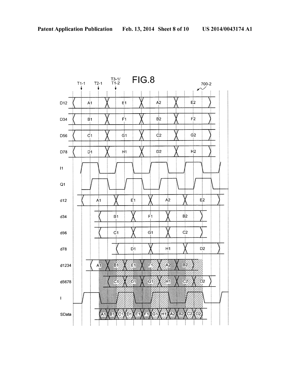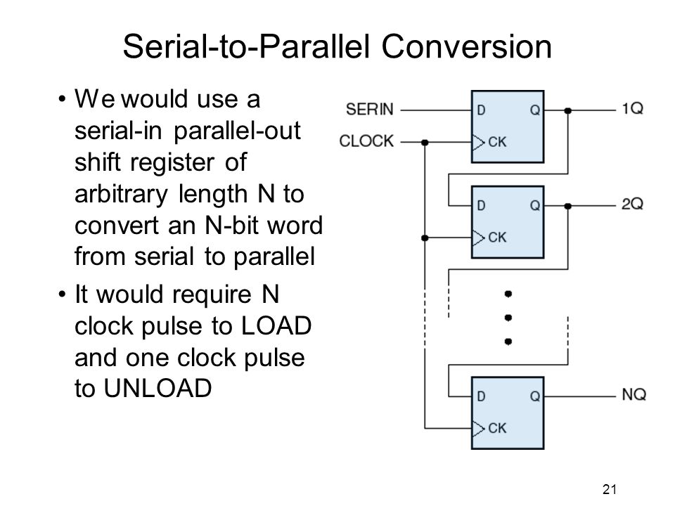

First serial output bit is the MSB of the input parallel data. In Figure4 is reported a simulation of the parallel to serial converter VHDL code above. The clock is set to 10 ns, so 80 ns mean 8 clock cycles. In the simulation of all the figures below, It is clear that the FIFO depth shall be sized depending on the input data timing and, in any cases, the input data rate shall be less than or, at least, equal to the output serial data rate as in equation EQ1 ParallelDataRate <= SerialDataRate * N EQ1 Parallel to serial converter VHDL simulation results

The read fifo logic will enable the read fifo data each 1/N clock cycles. If you need to handle different input timing you can implement a simple input FIFO logic in order to buffer the incoming parallel data. I mean, if the parallel data is not yet totally serialized, no other input data can be processed. The error detection logic rises the “ o_error_serialize_pulse” if the input data enable is high during the serialization process. In the VHDL code is implemented an error detection logic. Signal r_data : std_logic_vector(G_N-1 downto 0) O_error_serialize_pulse : out std_logic) I_data : in std_logic_vector(G_N-1 downto 0) Figure 2 Parallel to Serial conversion exampleĪn example of Parallel to Serial converter The serializer section takes N clock cycles to output the serial data stream. The parallel input to the module shall be at a rate of less than or equal to 1/N clock cycles. Let assume the parallel data bus of the Parallel to Serial converter to be N bit. Parallel to Serial converter VHDL code example

If you need to transfer 16-bit data 1MHz the serial data stream speed shall be at least greater than 16 x 1 MHz = 16 MHz. Same data rate you need to use a higher speed in data transfer. Figure 1 FPGA connection Parallel vs SerialĬould be to serialize the parallel data using less connection. As you can see, these are a lot of wires! Moreover, a skew between the bits in the parallel data bus can affect the connection integrity. For instance, if we need to transfer a data bus of 16 bits between twoĭifferent FPGA at a rate of 1 MHz, we need to connect at leastġ6-bit data + 1 bit enable + 1 bit clock = 18 wires running 1 MHz. From two different devices, the simple way is to use the minimum numbers of


 0 kommentar(er)
